Interactive guide
Neon flex wiring guide
How to wire Tunable single colour, RGB(W) and tunable white neon flex, respect its bending diameters, cut it, and fit the solder-free cable feed and end cap.
Scroll to follow the wiringWiring diagrams by neon flex type
Scroll through each neon flex type in turn, or jump to one. Each diagram shows the driver or controller terminals and the wire colours into the neon flex cable feed. Two runs are shown wired in parallel.
Single colour neon flex (2700K, 3000K, 4000K)
Driver
24V LED Driver
Start at the 24V LED Driver. Every wire in this diagram runs from its terminal block.
Power in
Mains supply
The mains supply connects to terminals L, N and earth (⏚).
Terminals
Output terminals
Top to bottom: V− and V+.
Wire 1 of 2
Black wire (V−)
From terminal V− to the cable feed on both neon flex runs.
- Terminal
- V−
- Wire
- Black (V−)
- Neon flex
- Cable feed, both runs
Wire 2 of 2
Red wire (V+)
From terminal V+ to the cable feed on both neon flex runs.
- Terminal
- V+
- Wire
- Red (V+)
- Neon flex
- Cable feed, both runs
Cable feed
Neon flex cable feed
Each run takes the same 2 wires through its cable feed: the two runs are wired in parallel.
Light
Current flows
Current flows from the 24V LED Driver to the neon flex. Lit in warm white once current arrives.Lit in warm white once current arrives.
| Terminal | Wire | Neon flex |
|---|---|---|
| V− | Black (V−) | Cable feed, both runs |
| V+ | Red (V+) | Cable feed, both runs |
RGB(W) neon flex (Red, Blue, Green, 3000K White)
Controller
4 Channel PWM
Start at the 4 Channel PWM. Every wire in this diagram runs from its terminal block.
Power in
POWER
The 24V DC supply from a 24V LED driver connects to the POWER input.
Terminals
Output terminals
Top to bottom: W, B, G, R and V+.
Wire 1 of 5
White wire (W)
From terminal W to the cable feed on both neon flex runs.
- Terminal
- W
- Wire
- White (W)
- Neon flex
- Cable feed, both runs
Wire 2 of 5
Blue wire (B)
From terminal B to the cable feed on both neon flex runs.
- Terminal
- B
- Wire
- Blue (B)
- Neon flex
- Cable feed, both runs
Wire 3 of 5
Green wire (G)
From terminal G to the cable feed on both neon flex runs.
- Terminal
- G
- Wire
- Green (G)
- Neon flex
- Cable feed, both runs
Wire 4 of 5
Red wire (R)
From terminal R to the cable feed on both neon flex runs.
- Terminal
- R
- Wire
- Red (R)
- Neon flex
- Cable feed, both runs
Wire 5 of 5
Black wire (V+)
From terminal V+ to the cable feed on both neon flex runs.
- Terminal
- V+
- Wire
- Black (V+)
- Neon flex
- Cable feed, both runs
Cable feed
Neon flex cable feed
Each run takes the same 5 wires through its cable feed: the two runs are wired in parallel.
Light
Current flows
Current flows from the 4 Channel PWM to the neon flex. Once lit, it cycles through the red, green, blue and 3000K white channels.Keep scrolling to step through the red, green, blue and 3000K white channels.
| Terminal | Wire | Neon flex |
|---|---|---|
| W | White (W) | Cable feed, both runs |
| B | Blue (B) | Cable feed, both runs |
| G | Green (G) | Cable feed, both runs |
| R | Red (R) | Cable feed, both runs |
| V+ | Black (V+) | Cable feed, both runs |
Tunable white neon flex (2700K – 6500K)
Driver
DT8 Tunable White LED Driver
Start at the DT8 Tunable White LED Driver. Every wire in this diagram runs from its terminal block.
Power in
Power input
The supply connects to the power input.
Terminals
Output terminals
Top to bottom: LEDV−, LEDV+, LEDV− and LEDV+. The second terminal (LEDV+) is not connected.
Wire 1 of 3
Yellow wire (WW)
From terminal LEDV− to the cable feed on both neon flex runs.
- Terminal
- LEDV−
- Wire
- Yellow (WW)
- Neon flex
- Cable feed, both runs
Wire 2 of 3
Brown wire (V+)
From terminal LEDV+ to the cable feed on both neon flex runs.
- Terminal
- LEDV+
- Wire
- Brown (V+)
- Neon flex
- Cable feed, both runs
Wire 3 of 3
White wire (W)
From terminal LEDV− to the cable feed on both neon flex runs.
- Terminal
- LEDV−
- Wire
- White (W)
- Neon flex
- Cable feed, both runs
Cable feed
Neon flex cable feed
Each run takes the same 3 wires through its cable feed: the two runs are wired in parallel.
Light
Current flows
Current flows from the DT8 Tunable White LED Driver to the neon flex. Once lit, it sweeps between warm (2700K) and cool (6500K) white.Keep scrolling to sweep from warm (2700K) to cool (6500K) white.
| Terminal | Wire | Neon flex |
|---|---|---|
| LEDV− | Yellow (WW) | Cable feed, both runs |
| LEDV+ | Brown (V+) | Cable feed, both runs |
| LEDV− | White (W) | Cable feed, both runs |
Bending diameter
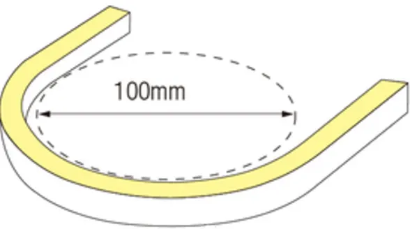
Horizontal Bend 100mm 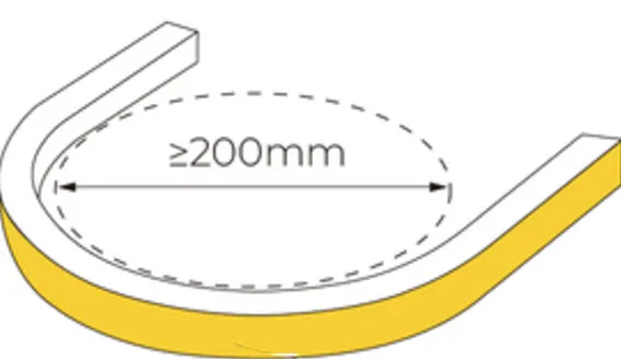
Vertical Bend ≥200mm 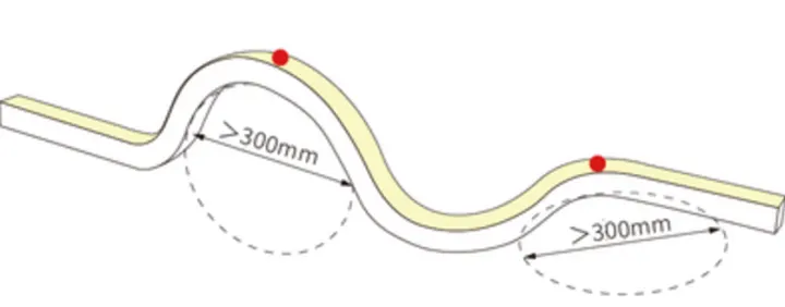
3D Bend >300mm
General installation
Avoiding damage during installation
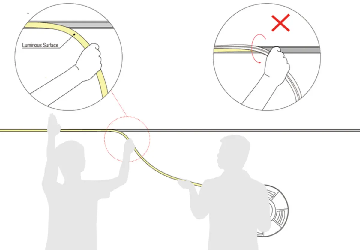
Installer
Press lightly with the palm of your hand slowly pushing the neon into the profile, noting to not bend the neon
Assistant
Slowly feed the neon off the provided reel, ensuring a straight smooth feed with no kinks or twists
Cable information
| Type | Cable | Inner core | Wire colours |
|---|---|---|---|
| RGBW neon flex | Inner core: 24AWG |
|
|
| Tunable white neon flex | Inner core: 22AWG |
|
|
| Single colour neon flex | Inner core: 20AWG |
|
Cutting directions
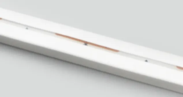
The Neon Flex has a transparent window, with the black marker being the cut marker
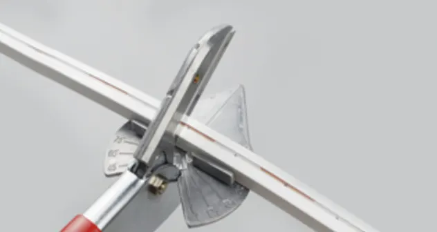
Using specialized scissors (sold separately) cut vertically at the mark
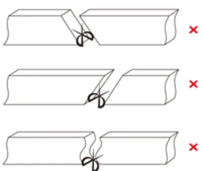
Ensure a straight clean cut is made, and not to cut at an angle to cause damage to the product
Please note: cutting neon flex should only be used for indoor application and will void any IP ratings.
Using solder-free cable feed
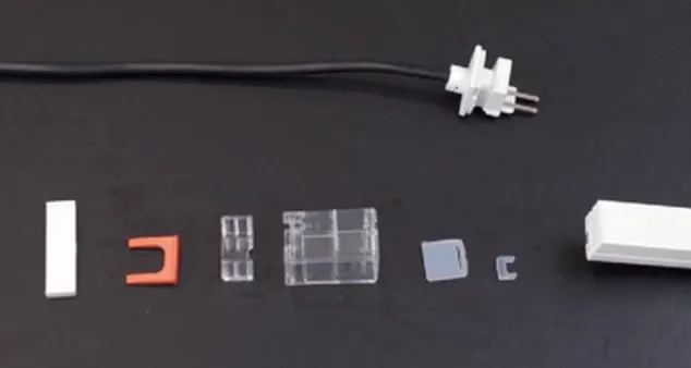
The Kit includes the following from left to right: Aligner, Orange Clip, Clear Clip, End Cap, Silicone Gasket, Spacer Clip
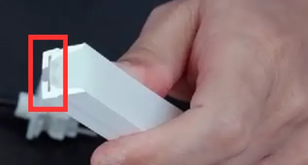
Slide the Space Clip into the Neon Flex between the LED Board & Silicone
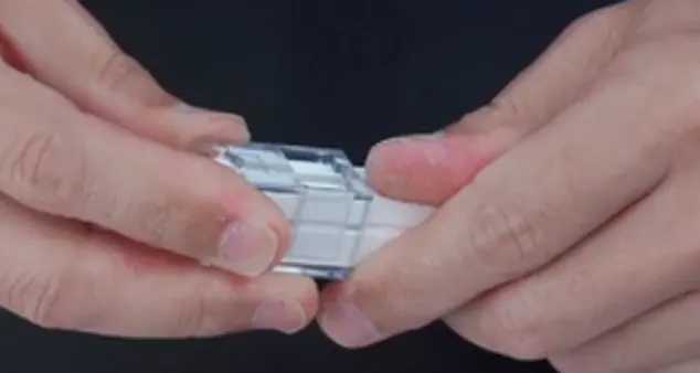
Slide the End Cap over the Neon Flex, ensuring a snug tight fit. The Gap in the plastic should be at the bottom of the Neon Flex
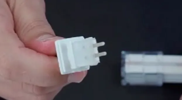
Insert the Silicone Gasket over the Cable Feed prongs
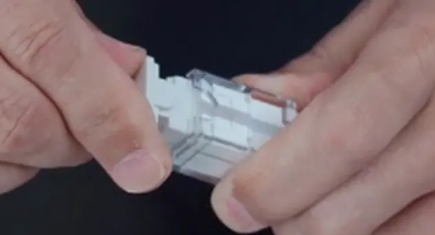
Insert the Cable Feed into the Neon Flex, with the power prongs sitting underneath the LED Board
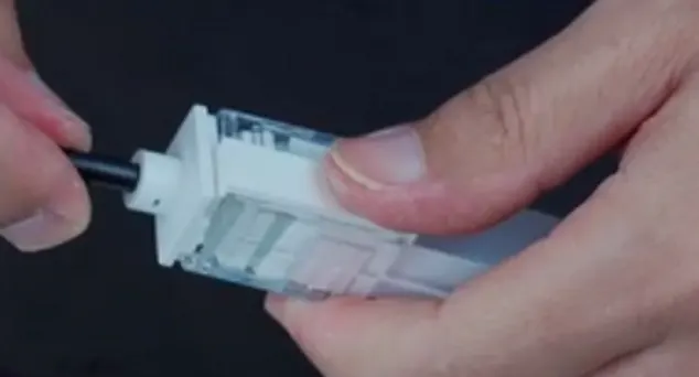
Use the Aligner to correctly space the clips for the next steps. Once aligned, it can be put aside as it is not used for the finished product
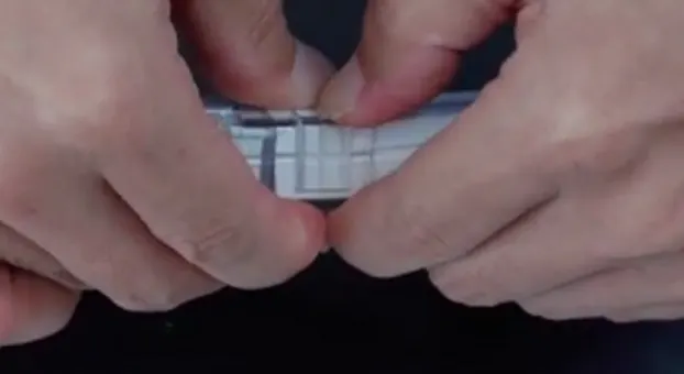
Push the Clear Clip into the gap on the on the bottom of the end cap, this is for structural purposes
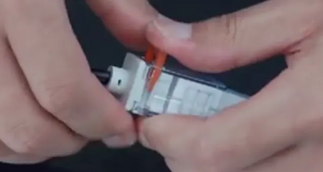
Rotate the Neon Flex, 180°. With the space created at the end of the Neon Flex by the Aligner in Step. 6, slide the orange clip in between the End Cap & Cable Feed
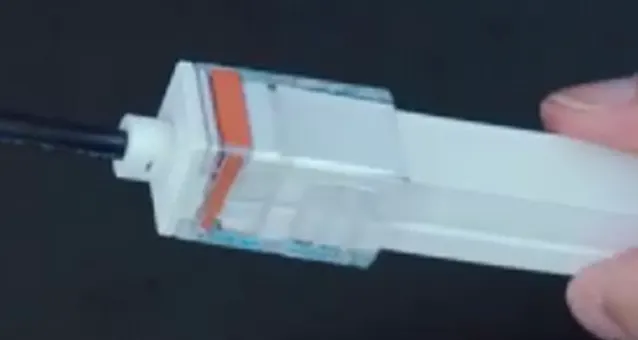
The finished product should look like this. Gently pull on the wire to ensure a tight snug fit has been achieved.
Using solder-free end cap
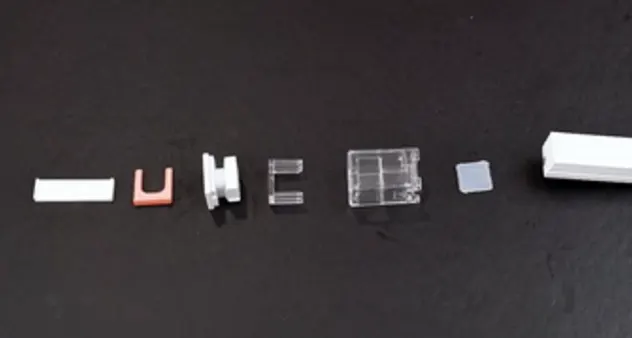
The Kit includes the following from left to right: Aligner, Orange Clip, End Stop, Clear Clip, End Cap, Silicone Gasket
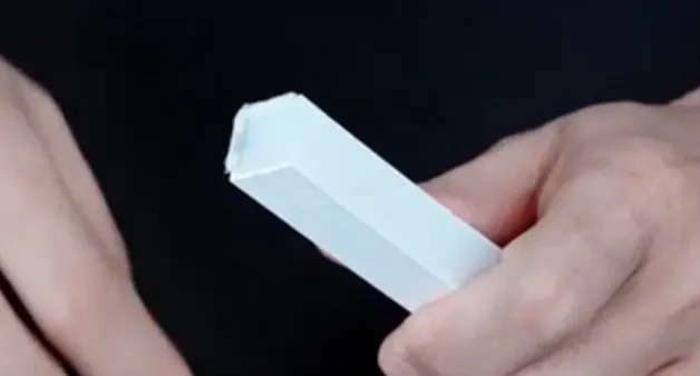
Place the Silicone Gasket on the end of the Neon Flex where you have cut
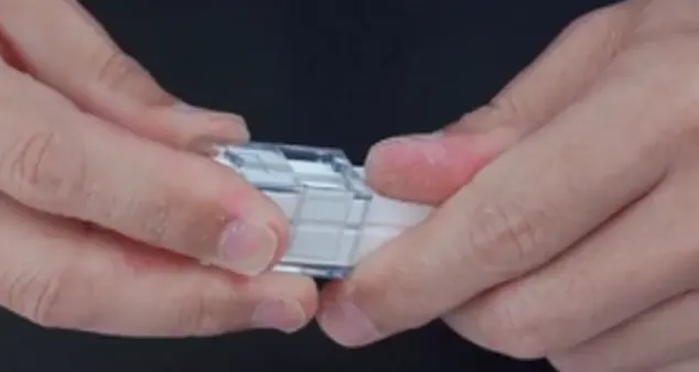
Slide the End Cap over the Neon Flex, ensuring a snug tight fit. The Gap in the plastic should be at the bottom of the Neon Flex
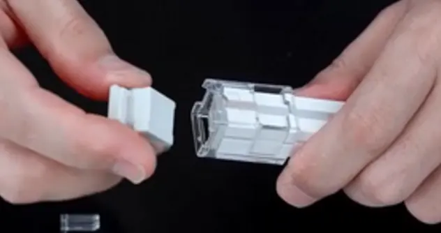
Insert the End Stop into the End Stop
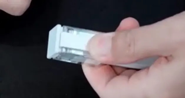
Use the Aligner to correctly space the clips for the next steps. Once aligned, it can be put aside as it is not used for the finished product
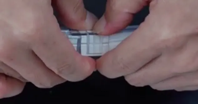
Push the Clear Clip into the gap on the on the bottom of the end cap, this is for structural purposes
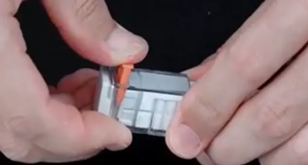
Rotate the Neon Flex, 180°. With the space created at the end of the Neon Flex by the Aligner in Step. 6, slide the orange clip in between the End Cap & Cable Feed
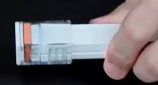
The finished product should look like this. Gently pull on the wire to ensure a tight snug fit has been achieved.
Request a quote
Have a project in mind?
Illuminate your space with our lighting solutions. Our lighting specialists are ready to assist you with all the information you require.