Interactive guide
LED strip wiring guide
How to wire Tunable single colour, RGB(W) and tunable white LED strip to its driver or PWM controller, join it with solder-free connectors, and install it without damage.
Scroll to follow the wiringWiring diagrams by strip type
Scroll through each strip type in turn, or jump to one. Each diagram shows the driver or controller terminals, the wire colours and the solder pads on each Tunable strip, followed by the solder-free connector steps for that strip.
Single colour LED strip (2700K, 3000K, 4000K)
Driver
24V LED Driver
Start at the 24V LED Driver. Every wire in this diagram runs from its terminal block.
Power in
Mains supply
The mains supply connects to terminals L, N and earth (⏚).
Terminals
Output terminals
Top to bottom: V− and V+.
Wire 1 of 2
Black wire (V−)
From terminal V− to the matching pad on each strip.
- Terminal
- V−
- Wire
- Black (V−)
- tunable Vitta COB LED Strip
- −
- tunable Pila & Summus SMD LED Strip
- −
Wire 2 of 2
Red wire (V+)
From terminal V+ to the matching pad on each strip.
- Terminal
- V+
- Wire
- Red (V+)
- tunable Vitta COB LED Strip
- +24V
- tunable Pila & Summus SMD LED Strip
- +24V
Pads
Strip solder pads
- tunable Vitta COB LED Strip +24V, −
- tunable Pila & Summus SMD LED Strip +24V, −
Light
Current flows
Current flows from the 24V LED Driver to the strip. Lit in warm white once current arrives.Lit in warm white once current arrives.
| Terminal | Wire | tunable Vitta COB LED Strip pad | tunable Pila & Summus SMD LED Strip pad |
|---|---|---|---|
| V− | Black (V−) | − | − |
| V+ | Red (V+) | +24V | +24V |
Solder-free connector installation (strip to strip)
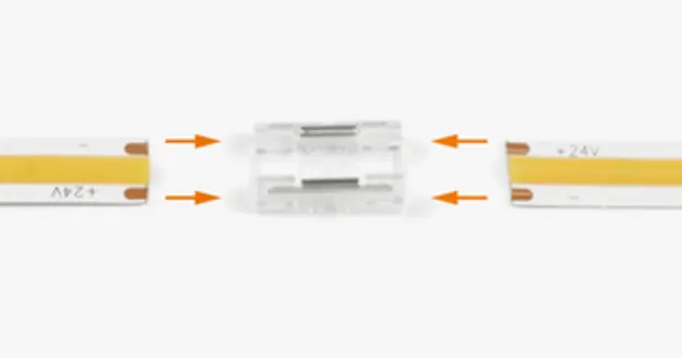
Insert the strip into the connector
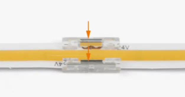
Ensure solder pads on the strip make contact with all pins in the connector
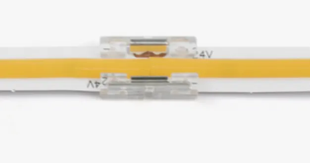
Press down on the pins so that they make a tight and secure contact
Solder-free connector installation (strip to cable)
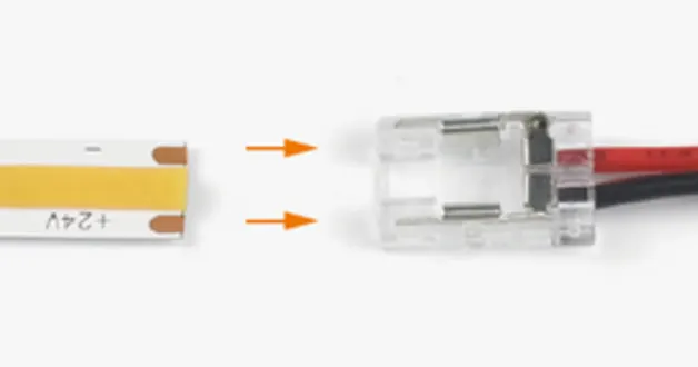
Insert the strip into the connector
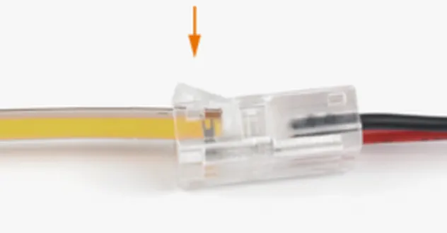
Ensure solder pads on the strip make contact with all pins in the connector
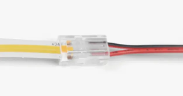
Press down on the pins so that they make a tight and secure contact
RGB(W) LED strip (Red, Blue, Green, 3000K White)
Controller
4 Channel PWM
Start at the 4 Channel PWM. Every wire in this diagram runs from its terminal block.
Power in
POWER
The 24V DC supply from a 24V LED driver connects to the POWER input.
Terminals
Output terminals
Top to bottom: W, B, G, R and V+.
Wire 1 of 5
White wire (W)
From terminal W to the matching pad on each strip.
- Terminal
- W
- Wire
- White (W)
- tunable Litus COB LED Strip
- W
- tunable Vicis SMD LED Strip
- W
Wire 2 of 5
Blue wire (B)
From terminal B to the matching pad on each strip.
- Terminal
- B
- Wire
- Blue (B)
- tunable Litus COB LED Strip
- B
- tunable Vicis SMD LED Strip
- B
Wire 3 of 5
Green wire (G)
From terminal G to the matching pad on each strip.
- Terminal
- G
- Wire
- Green (G)
- tunable Litus COB LED Strip
- G
- tunable Vicis SMD LED Strip
- G
Wire 4 of 5
Red wire (R)
From terminal R to the matching pad on each strip.
- Terminal
- R
- Wire
- Red (R)
- tunable Litus COB LED Strip
- R
- tunable Vicis SMD LED Strip
- R
Wire 5 of 5
Black wire (V+)
From terminal V+ to the matching pad on each strip.
- Terminal
- V+
- Wire
- Black (V+)
- tunable Litus COB LED Strip
- +24V
- tunable Vicis SMD LED Strip
- +24V
Pads
Strip solder pads
- tunable Litus COB LED Strip +24V, W, B, G, R
- tunable Vicis SMD LED Strip +24V, W, B, G, R
Light
Current flows
Current flows from the 4 Channel PWM to the strip. Once lit, it cycles through the red, green, blue and 3000K white channels.Keep scrolling to step through the red, green, blue and 3000K white channels.
| Terminal | Wire | tunable Litus COB LED Strip pad | tunable Vicis SMD LED Strip pad |
|---|---|---|---|
| W | White (W) | W | W |
| B | Blue (B) | B | B |
| G | Green (G) | G | G |
| R | Red (R) | R | R |
| V+ | Black (V+) | +24V | +24V |
Solder-free connector installation (strip to strip)
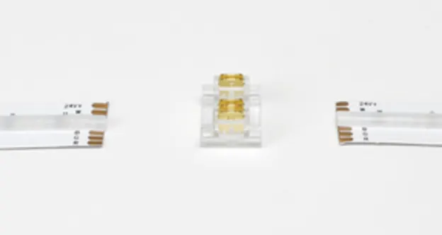
Insert the strip into the connector
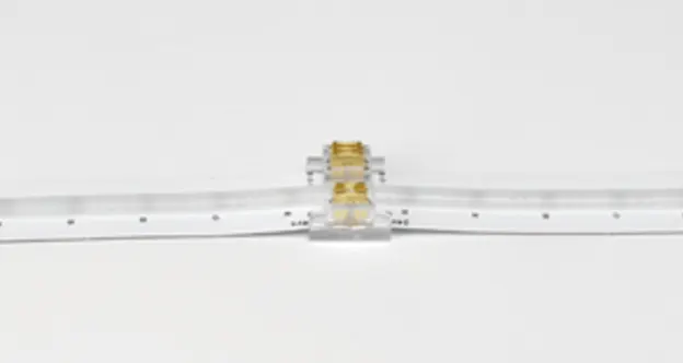
Ensure solder pads on the strip make contact with all pins in the connector
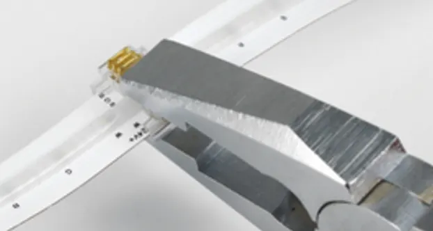
Press down on the pins so that they make a tight and secure contact
Solder-free connector installation (strip to cable)
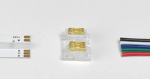
Insert the strip into the connector
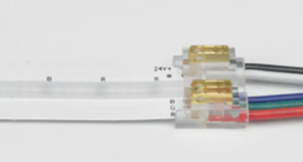
Ensure solder pads on the strip make contact with all pins in the connector
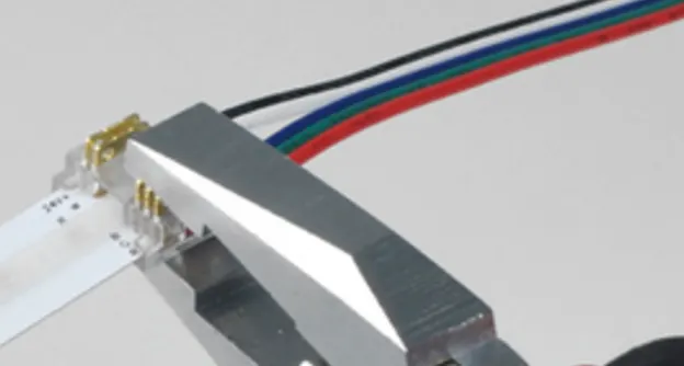
Press down on the pins so that they make a tight and secure contact
Tunable white LED strip (2700K – 6500K)
Driver
DT8 Tunable White LED Driver
Start at the DT8 Tunable White LED Driver. Every wire in this diagram runs from its terminal block.
Power in
Power input
The supply connects to the power input.
Terminals
Output terminals
Top to bottom: LEDV−, LEDV+, LEDV− and LEDV+. The second terminal (LEDV+) is not connected.
Wire 1 of 3
Yellow wire (WW)
From terminal LEDV− to the matching pad on each strip.
- Terminal
- LEDV−
- Wire
- Yellow (WW)
- tunable Litus COB LED Strip
- W
- tunable Vicis SMD LED Strip
- WW
Wire 2 of 3
Brown wire (V+)
From terminal LEDV+ to the matching pad on each strip.
- Terminal
- LEDV+
- Wire
- Brown (V+)
- tunable Litus COB LED Strip
- +24V
- tunable Vicis SMD LED Strip
- +24V
Wire 3 of 3
White wire (W)
From terminal LEDV− to the matching pad on each strip.
- Terminal
- LEDV−
- Wire
- White (W)
- tunable Litus COB LED Strip
- C
- tunable Vicis SMD LED Strip
- W
Pads
Strip solder pads
- tunable Litus COB LED Strip +24V, C, W
- tunable Vicis SMD LED Strip +24V, W, WW
Light
Current flows
Current flows from the DT8 Tunable White LED Driver to the strip. Once lit, it sweeps between warm (2700K) and cool (6500K) white.Keep scrolling to sweep from warm (2700K) to cool (6500K) white.
| Terminal | Wire | tunable Litus COB LED Strip pad | tunable Vicis SMD LED Strip pad |
|---|---|---|---|
| LEDV− | Yellow (WW) | W | WW |
| LEDV+ | Brown (V+) | +24V | +24V |
| LEDV− | White (W) | C | W |
Solder-free connector installation (strip to strip)
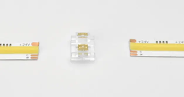
Insert the strip into the connector
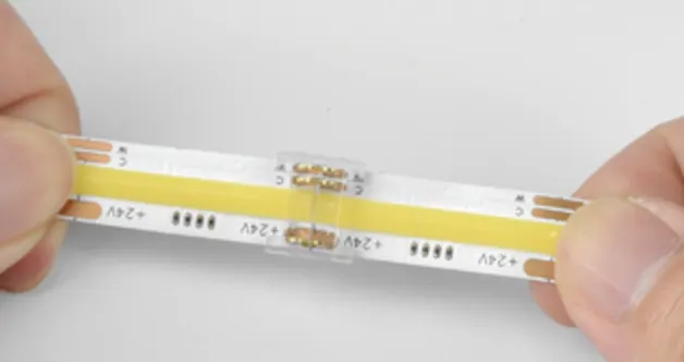
Ensure solder pads on the strip make contact with all pins in the connector
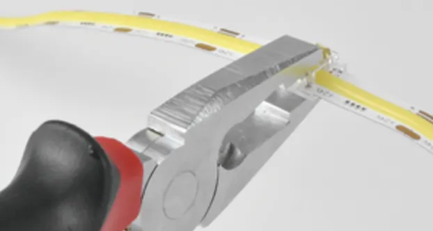
Press down on the pins so that they make a tight and secure contact
Solder-free connector installation (strip to cable)
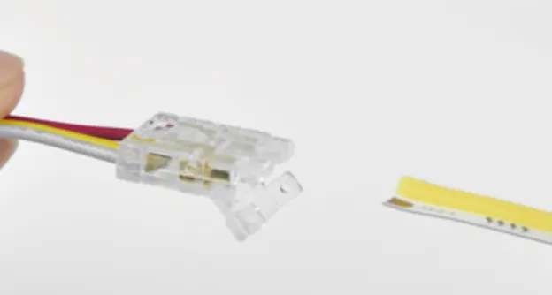
Insert the strip into the connector
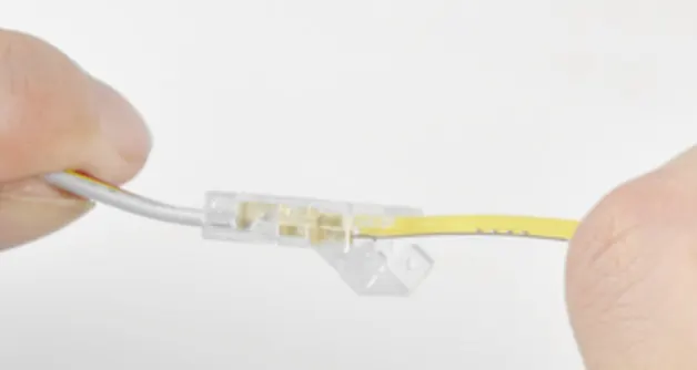
Ensure solder pads on the strip make contact with all pins in the connector
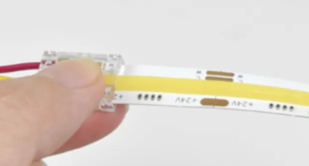
Press down on the pins so that they make a tight and secure contact
General installation
Avoiding damage during installation
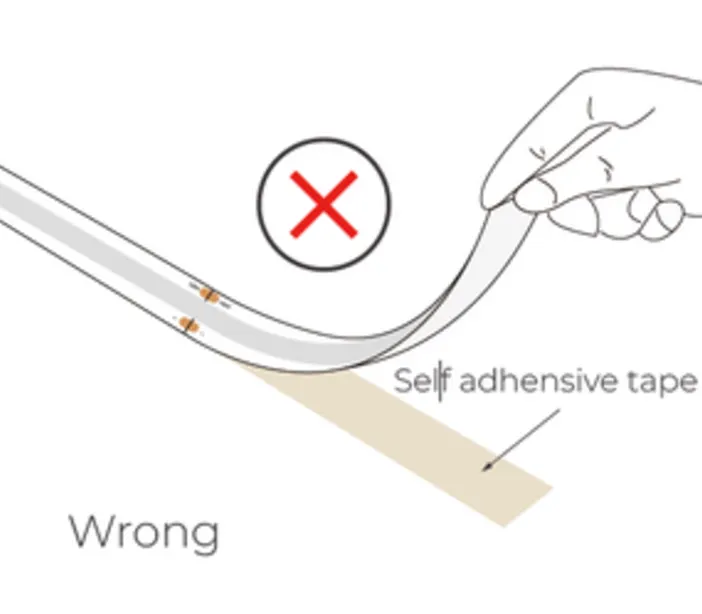
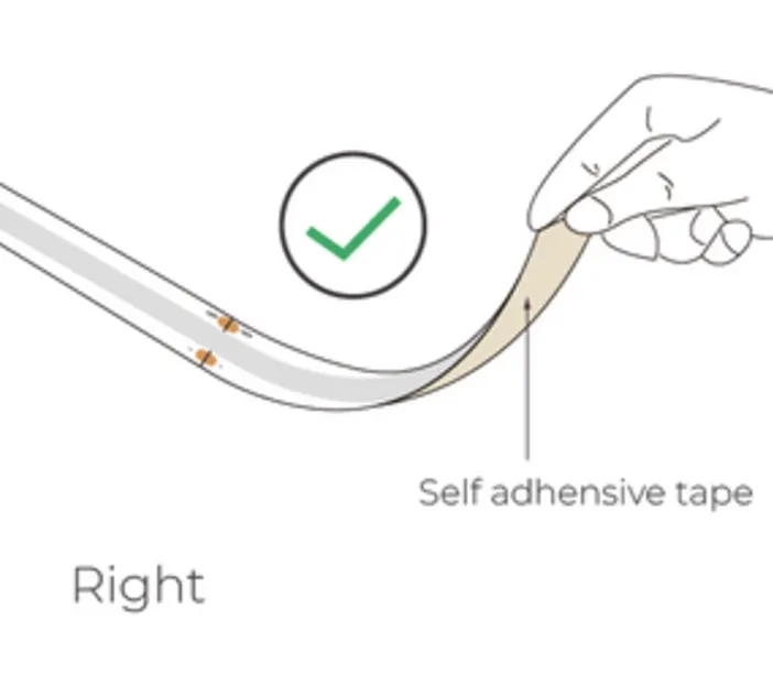
If the strip needs to be pulled up for repositioning, ensure that the self adhesive tape is also pulled to avoid damaging the strip.
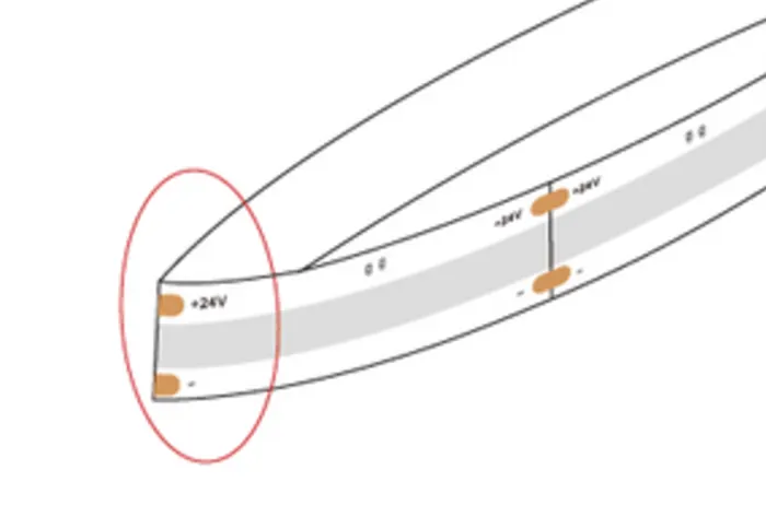
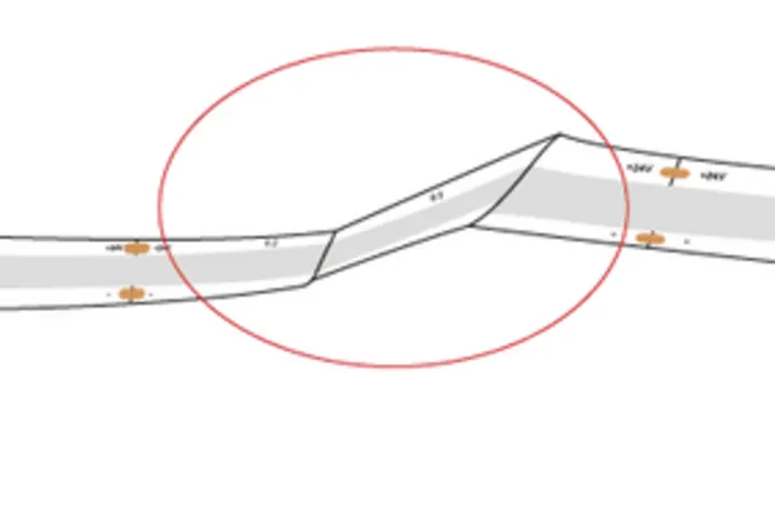
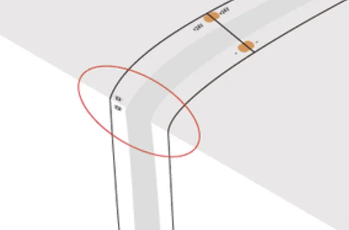
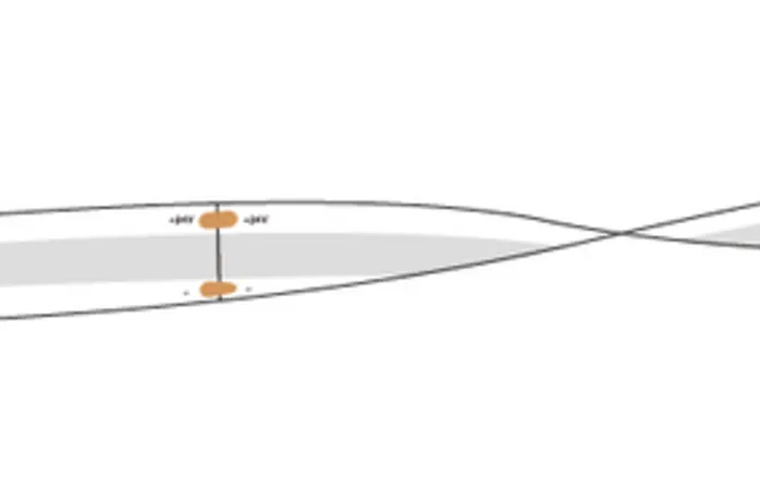
When handling the strip, ensure to not bend or twist the strip to avoid cracking the solder points and damaging the LEDs
Cable information
| Type | Cable | Inner core | Wire colours |
|---|---|---|---|
| RGBW LED Strip | Inner core: 24AWG |
|
|
| Tunable White LED Strip | Inner core: 22AWG |
|
|
| Single Colour LED Strip | Inner core: 22AWG |
|
Request a quote
Have a project in mind?
Illuminate your space with our lighting solutions. Our lighting specialists are ready to assist you with all the information you require.